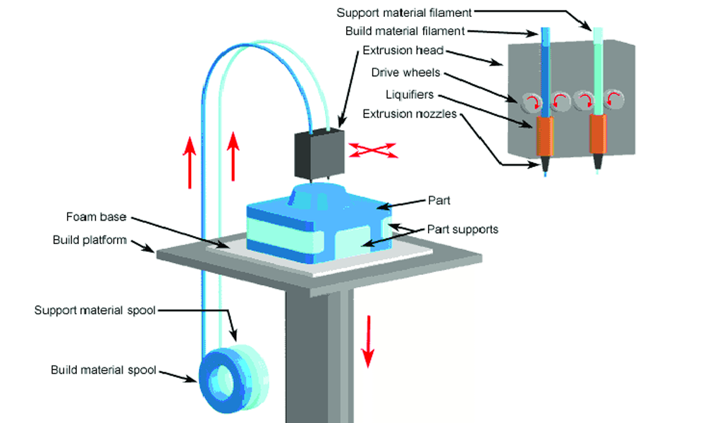
Fused Deposition Modeling (FDM) is another widely used rapid prototyping process following light-curing rapid prototyping and stacked solid rapid prototyping processes. The technology is currently more widely used a 3D printing technology, but also one of the earliest open source 3D printing technology.

Ⅰ. Printing parameters of FDM 3D printer
① nozzle temperature, the nozzle should be heated above the glass transition temperature (melting point of plastic) of the plastic filament so that it can flow like a liquid. Temperatures that are too low will not fully melt the filament and may clog the print nozzle. The glass transition temperature of PLA is about 180 degrees Celsius.
② Print bed temperature. Sometimes it is necessary to preheat the print bed to prevent warpage of the part. Warpage is a common defect in FDM and is caused by a higher temperature gradient between the printed part, which is at a high temperature, and the print bed. Generally when using ABS filament, the print bed needs to be preheated to over 100 degrees Celsius to prevent warpage.
③ Layer thickness, which is actually the thickness of each layer, is a parameter that largely determines part resolution. Smaller layer thicknesses achieve higher resolution, accuracy and smooth surfaces, but can significantly increase print time. FDM can be adjusted for layer thicknesses ranging from 50 to 400 microns. Typically a layer thickness of 200 microns can be selected.
④ Shell thickness and infill density, the actual 3D printed part is not completely solid, it is usually composed of a certain thickness of the contour (i.e., shell), as well as a low-density infill structure. Infill density is actually equivalent to volume percentage (from 0% to 100%), where 0% indicates a hollow interior and 100% indicates a solid interior. The filling can also have different shapes, such as honeycomb, rectangular, and diamond. The thickness of the shell and the filling density affect the strength of the part. Typically the default settings for shell thickness and infill density are 1mm and 25% respectively. Such settings greatly reduce printing time and material consumption.
Ⅱ. Features of Fused Deposition Rapid Prototyping
Fused deposition rapid prototyping (FDM) development is so rapid, mainly because it has the following advantages that other processes can not be compared:
① Fused deposition rapid prototyping technology does not use lasers, so that not only the operation is simple, but also lower manufacturing costs for companies.
② fused deposition rapid prototyping technology is a plastic filament, this material is easier to clean compared with other materials, but also easy to replace later, which is the main advantage of the FDM process, especially compared with powder and liquid material process, this filament will not be formed in the equipment of the powder or liquid contamination. fdm process is another major advantage of the material properties of the prototype strength of the ABS can be up to 1/3 of the injection molded parts, and more recently, it is also a major advantage of the FDM process is that the material properties of ABS prototype strength can reach the injection molded parts. 1/3 of the parts, and recently several new materials, PC, PPSF, etc., these materials can be used directly in some specific applications, with the further improvement of material properties and process level, there will be more FDM prototypes in a variety of occasions for direct use.
③ Post-processing is simple. Fused deposition rapid prototyping technology requires only a few minutes to a quarter of an hour after peeling off the support, the prototype can be used.
④Faster molding speed. Generally speaking, the FDM process is slower compared to other processes, but it also has certain advantages. When the strength of the prototype is not required, the FDM molding speed can be increased by reducing the degree of compactness of the prototype.
Summarize:
Advantages:
1)The system construction principle and operation are simple, low maintenance cost, and safe system operation.
2) Non-toxic raw materials can be used, and the equipment system can be installed and used in an office environment.
3)The prototype of parts molded in wax can be directly used for lost wax casting.
4) Parts of any complexity can be molded, often used for molding parts with very complex cavities and holes.
5)There is no chemical change of raw materials in the molding process, and the warping and deformation of the parts are small.
6) High utilization rate of raw materials, and long life of materials.
7) Support removal is simple, no chemical cleaning, easy to separate.
Disadvantages:
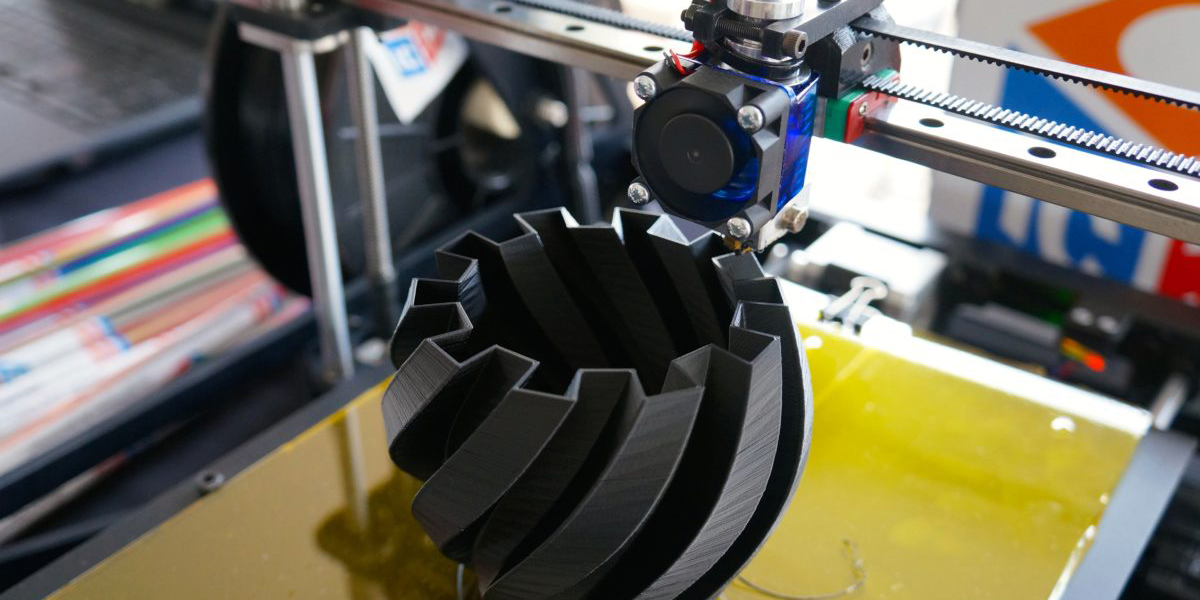
1)The surface of the molded part has more obvious stripes.
2)Weaker strength along the vertical direction of the molding axis.
3)Requires design and fabrication of support structure.
4)Requires scanning coating of the entire cross-section and longer molding time.
5)Raw materials are expensive.

III. Material Application
For 3D printing, the material is the key, FDM technology path involves materials mainly including molding materials and support materials, according to the technical characteristics of the molding material is required to have a low melting temperature, low viscosity, good adhesion, small shrinkage, etc., the support material is required to have the ability to withstand a certain amount of high temperature, and the molding material is not infiltrated, with a water-soluble or acid-soluble, and has a low melting temperature, The support material should be able to withstand certain high temperature, not infiltrated with the molding material, water-soluble or acid-soluble, have a low melting temperature, and have good fluidity.
The main materials used in FDM 3D printing technology are ABS (AcylonitrileButadiene Styrene, a copolymer of acrylic eye, butadiene and styrene) and PLA (PolylacticeAcid, biodegradable plastic polylactic acid).
(1) ABS plastic
ABS plastic has excellent overall performance, its strength, flexibility, excellent machinability, and has a higher temperature resistance, is the engineering machinery parts of the preferred plastic.
The disadvantage of ABS plastic is that it produces odor during the printing process, and because of the cold shrinkage of ABS, the model is easy to detach from the print plate during the printing process.
(2) PLA plastic
PLA plastic is one of the most widely used materials in current desktop 3D printers.PLA plastic is a biodegradable material made from starch feedstock proposed using renewable plant resources (e.g. corn).
IV. Analysis of factors affecting the accuracy of fused deposition rapid prototyping
①. Principle error
(1) Errors in the fitting of CAD models to STL files. We often use STL file format in the field of rapid prototyping, STL file data processing is to discrete the model into a multi-layer contour, and then in various ways to fill a complex model, through the conversion of the resulting STL file contains millions of triangular surface pieces. Especially when multiple surfaces are triangulated, there will be more errors and defects at the intersection of the surfaces, which greatly reduces the accuracy of the model. However, we can add a certain number of triangular facets to achieve the effect of reducing the geometric errors, which can improve the model approximation accuracy to a large extent. Generally the chord height is used to control the geometric error, ε denotes the chord height, which refers to the radial distance between the contour edge of the approximated triangle and the surface.
(2) Errors in the slicing process. By slicing the solid, not only can the process be simplified, but at the same time, the geometric interference problem in machining is completely solved. However, there is a certain distance between each slicing layer, which destroys the continuity of the model surface, and the greater the thickness of the layering, the more information is lost between the two slicing layers, which leads to not only the shape error of the prototype, but also a large size error.
②. Errors in the molding process
In the FDM process molding process, the error mainly exists in the FDM equipment itself inherent process parameters or user-set process control parameters, different process parameters caused by different processing time, and different process parameters caused by the molding accuracy is also very different.
(1). Molding temperature. Molding temperature includes two parts:
1) . ambient temperature;
2). nozzle temperature.
Ambient temperature refers to the temperature of the environment around the prototype when the system works, usually refers to the temperature of the molding chamber. Ambient temperature mainly affects the surface quality of molded parts, if the temperature is too low, it will make the molded parts thermal stress increases, easily caused by parts warping and deformation, and at lower temperatures, extrusion filament cooling speed, the first layer of the cross-section has been completely cooled and solidified before they begin to pile up after a layer, leading to the interlayer bond is not strong, the parts will be cracked; if the temperature is too high, the first layer of silk is not fully cured, after a layer of silk will be If the temperature is too high, the first layer of silk is not fully cured, the latter layer of silk will start to pile up, it will make the surface of the parts to produce "collapse" phenomenon. Nozzle temperature is the working temperature when the nozzle is heated to a certain value, in general, the optimal temperature of the nozzle is to keep the silk in the molten state, the molten state is the state between the solid and the liquid, so that the viscosity coefficient of the material to remain within a stable range, if the silk extrusion speed is reasonable, it will be uniformly out of the silk, to avoid the phenomenon of peeling off the level.
(2) Extrusion speed and scanning speed.
Extrusion speed refers to the speed of the silk extrusion nozzle, while the scanning speed refers to the speed of the silk with the movement of the nozzle, because each layer of the molded parts are closed geometric boundaries, and each closed geometric boundaries there are starting and stopping points, the extrusion speed and scanning speed to have a reasonable range of matches, so that you can avoid excess or insufficient material, in order to get a higher accuracy of the parts, if the extrusion speed and the scanning speed is less than this reasonable range of matches, so as to avoid material surplus or shortage, in order to get higher accuracy of the parts. If the extrusion speed and scanning speed is less than this reasonable matching range, it will produce "pulling" or "broken wire" phenomenon, seriously affecting the accuracy of the parts; if the extrusion speed and scanning speed beyond this reasonable matching range, it will lead to deformation of the parts, resulting in nozzle "carbonization" or "adhesion" phenomenon, hindering the next step of processing, so the extrusion speed and scanning speed should have a reasonable range.
(3) Delay time.
Delay time consists of two parts: the delay time of wire discharge when the switch is turned on and the delay time of wire breakage when the switch is turned off. When the switch is turned on, the wire feeding mechanism starts to feed the wire, but the nozzle has a certain delay, not immediately out of the wire, we call this period of time out of the wire delay time; when the wire feeding mechanism stops feeding the wire, however, the nozzle is still spraying material, not immediately out of the wire, there is a certain delay, we call this period of time out of the wire delay time. When the delay occurs, it will cause the phenomenon of under stacking; when the break delay occurs, it will cause excessive stacking phenomenon, the formation of "knots", so not only need to optimize the delay time out of the wire also need to optimize the break delay time, from the starting point of how far from the beginning of the start of the wire, from the end of how far from the end of the wire break.
(4) Filling method.
Filling method has a greater impact on the parts, not only related to the molding time, but also with the mechanical properties of the parts are closely related to the filling spacing is a crucial factor, if the filling spacing is too small, you can greatly improve the mechanical properties of the parts, but it will also have a negative impact on the processing time is longer, increasing costs; if the filling spacing is too large, although it can reduce processing time, reduce costs, but also Will greatly weaken the mechanical properties of the parts, in general, we take 1.5mm filling spacing.
③. Post-processing errors
In general, in order to improve the quality of the parts, the need to have molded the workpiece for post-processing, generally need to grind, polish and surface treatment, if the molded parts have a support structure also need to peel off the support structure, in the process of processing the following kinds of errors will generally occur:
(1) Since the support structure is closely combined with the workpiece, it is difficult to remove it, so in the process of removing the support structure, the surface quality of the workpiece is often affected, and if it is not operated properly, the surface of the workpiece will be scratched. In order to solve this problem, we can use water-soluble materials, which can remove the support structure well, but this way is more expensive. Therefore, before we design the molded parts, we should first consider the support method, and control the support spacing within a reasonable range, the general support spacing is 3mm, and when selecting the molding direction, we should choose a reasonable molding angle, so that we can avoid to a large extent the impact on the workpiece in the process of removing the support structure.
(2) As the environment around the workpiece will change over time, and environmental factors have a greater impact on the processed workpiece, in order to prevent the temperature, humidity and other causes of deformation of the workpiece, affecting the molding accuracy, so it should try to keep the environment around the workpiece, the general rapid prototyping of the curing time of 8 days, which should try to keep the workpiece within the surrounding environment within the 8d to keep the workpiece unchanged.
V. Application of fused deposition rapid prototyping technology
FDM application areas include conceptual modeling, functional prototyping, manufacturing processing, end-use part manufacturing, and finishing. It is widely used in the design and development process in automotive, machinery, aerospace, home appliances, communications, electronics, architecture, medicine, toys, etc., such as product appearance evaluation, program selection, assembly inspection, functional testing, user viewing and ordering, plastic parts calibration design before molding, and a small amount of product manufacturing, etc., and is also used in government, universities and research institutes. With the progress of technology, the application of FDM is still expanding.

Example: Application of FDM in Toyota, Japan
Toyota uses FDM process to make the right side mirror bracket and 4 door handles of the mother mold, through the rapid tooling technology to produce products and replace the traditional CNC molding method, so that the 2000 Avalon models of the significant reduction in the cost of manufacturing, the right mirror bracket mold cost reduction of 200,000 U.S. dollars, the cost of the 4 door handle molds to reduce the cost of 300,000 dollars. FDM process has been for the Toyota company in the car manufacturing savings of about 2 million dollars.
GET FREE FDM TECH SUPPORT